Saturday, May 21, 2011

Assignment Pt 1

Story

Rat was racing down the track in his car when suddenly he spotted a large hand drawing closer to his car from behind! He noticed that the hand came for the toy car's owner, George, a five-year old boy. Rat did not want his ride to end here, luckily he spotted the track ahead of him was going down and he might have the chance of escaping the hand for a couple of seconds. However, to his dismay, the boy was much faster than he anticipated, with the large enigmatic hand approaching and soon overshadowing Rat, he could only look in terror.

BAM! An object almost as large as himself miraculously landed in his car. It was a toy gun! Apparently George accidentally kicked it and it coincidently landed into Rat's hands. Rat used all his might to turn and aim the toy gun at the legs of the running boy who was grinning, thinking what to do with Rat when he caught him.


BANG! Rat hit the spot down came George, losing his balance and crashing into a pile of plushies leaning against the wall.

"Saaaaaaaaaaaaaaaaaaaaaaaafe!!!" Rat said to himself with glee.

Well, he is.. for now.

Shape

Well, what I'll be modeling for this assignment would be a semi-realistic looking pistol that fires plastic spherical projectile that Rat used against George.

The shapes used are generally not very basic as it requires plenty of modifications (explained later) to the primitive shapes in Maya. I will be breaking up my model into several parts to explain about what shapes I think I should use for these areas.
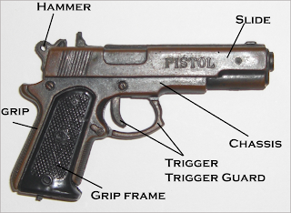


Slide
The basic shapes of the slide of the gun should be constructed with a cylinder - of course, with less subdivisions. I was thinking of using the polygon cube tool to construct this area and using the insert edge loops to create the barrel, I will post my results later on when I actually try both methods out.
as for the details (the words and the horse sign) I was thinking of using the draw polygon tool for the horse, for the text I can simply create 3D text and boolean difference it. The rest of the details could be done by simple beveling and extruding. I will start with the hammer and model towards the muzzle. The grip area can be extruded downwards from the barrel.

Chassis
The main chassis of the gun will be extruded downwards from the slide and extruded to form the body of the gun. Will be manipulating vertices to get the desired curved shapes and of course, inserting edge loops.

Grip
The grip area is quite straightforward, from the chassis, I will extrude it downwards to form the shape of the grip. Most likely I will only need to do extruding and the rest are minor details such as differences and vertices manipulation. The hard work will be to form a nice grip frame.

Trigger Guard/Trigger
The shape of the trigger guard will be extruded from either the grip or the slide, most likely I will do it from the grip and extrude it upwards to join with the main body of the gun. The trigger can either be extruded from the top OR creating a new shape, I will try both.

And that's it! The gun is only separated into 3 different parts and mostly everything here can be extruded from the slide. It is actually not very complicated. As you can see above, I mainly discussed plenty on the slide section; that section is where the whole gun will form from. That's why it is important and I dwell most of my views over at that section.

Design
Now... as for the design, I have mostly discussed what the design should be above. The only part detached from the body will most likely be details such as the slide stop, the hammer, the trigger and safety switches.

Sketches?! Bahh.... Later. I will be working on the model already.

Edit: Added
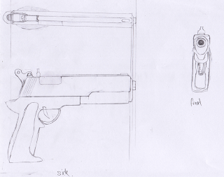

As for the parts, most of them are extruded, so I don't think that will be a problem :)

And yes, initially I did want to do a sketch that has all the dimensions right for all the views, but I ran out of space for the side(that's why it's slightly deformed), so next time if I decide to this, I will do this on a A3.......

Reference Images

In the above picture showing the parts I'm going to model, that will be my reference image. I was thinking whether do I need a front view reference, but since the breadth of the gun is not really important and the muzzle of the gun is simply just a hole, I think that a front view and a top view is not necessary at all. But I'll still ask my in-charge anyway.

Sunday, May 15, 2011

Mammoth Tank


Comments
The track and turret can be animation ready.
Other than that, I'm still practicing edgeflow and topology.
The more we do, the better we get.
The Mammoth Tank, Inspired by c&c3.

It was fun!


Process
This is a slightly complicated model(O.K not really).


Techniques


Setting up a proper Ref


Of course, in the above image, I have already resized, cut and altered the image to make it reference-friendly to me when imported into Maya. This set is VERY important. I stress it again, if you even want to use reference images, the images MUST correspond with each other. As you can see above, I used photoshop to align the joints and important areas to take note of when modeling in Maya.


When we are done resizing and altering the image to our hearts content, we can move on to importing the image to Maya. And oh, don't forget that in Maya, you will also have to do your required settings for the alignment and distance for your ref image which was briefly taught in class.

Making use of the Ref

Above:Right View


Above:Front View

It is a good habit to periodically check and manage your vertices for both right and front view. Then switching to perspective to check your model. (Or at least that is what I do.)


After a bit of extruding and inserting edge loops after planning, (Inserting edge loops are not random, it is usually done at places where you want to manipulate the vertices. After playing with it for some time you will naturally get it.) this is the image we get.

Tank Threads

In the above image, the foreground shows a weird shape, this will be the baseline for our tank threads. There are two main ways to derive to this shape - the cv curve tool or manipulating a polygon cube. I used the latter. Inserting edge loops at certain points(and places where I want to extrude to form the depth of the tracks) and moving, scaling the vertices to form this model.

Next, I would want to ....


So how is this done? It is pretty simple actually. Before this step, as explained before, I extruded certain faces on the threads before duplicating them(thats why there is some depth on the threads).
Basically, to duplicate such a nice round, you will have to adjust the center pivot to a favorable position and change into the rotate tool. Change the values(rotate on the x-axis) in the duplicate special tool so that the threads will look nicely together like shown above. (In this step, if we include a deformer, we can animate the threads to go in a loop.)


After adding some shapes, extruding, managing vertices I got this shown above. Duplicating the first one to form a clone on the left front wheel. Special note is taken to make sure the topology and edge flow is smooth.


Now, after adding certain details to the side wheels to make it more armory, I duplicated it and scaled it to form the longer back tank threads. I admit I got a little lazy here, I was actually supposed to redo the tank threads steps again but I got lazy. So I ended up duplicating it.

Well, after this step is basically adding the turret and building details on it.
That's how I derived to my final model.


In this post, what I really want to bring forth to help teach is not how to model a tank.
But rather, how to set up proper reference images. Because, it is hard to teach people how to actually do edge loops at certain important locations or teaching them which face to actually extrude. Rather, the person must find that out on their own.

That's what I think.

Model that I based on


Reference
Setting up Reference Images

Thinking Outside the Box

3DMindset & Learning

Does multi-tasking give you a real or false sense of having accomplished something?
Well, if you'd ask me, I would reply "It depends on the individual & the situation". This is answering the question - however, if applied to myself, I'd say multi-tasking actually fails; not only the quality of the produced result might drop, but the efficiency and rate of producing work will indubitably falter.

HOWEVER! Excluding the people who actually multi-tasks perfectly, the people who casually does it - for instance, a regular Singaporean Teenager studying for their O' Levels and someone texts him on his phone and he replies with glee then goes back to work. No matter how you see here, he actually wasted time checking his phone and replying. On the other hand, if you look at it this way - the person who texted him was his teacher, and he is asking various questions on the subject at hand - does this consider to be wasting time? Is multi-tasking really that bad?

In a nutshell, I think that for me, as a person, I'd say multi-tasking does not work for me but will give me a sense of satisfaction when I'd finish multiple jobs while doing that. But I do believe that multi-tasking really satisfies many people out there in the world and have made it big by doing it.

Is learning 3D and design different from learning programming, or is all learning the same?Why?
If learning was all the same, then why do people develop multiple ways to teach the same thing? Obviously learning language will not be the same as learning mathematics although they have few things in common - perserverance, attitude, willingness to learn and many more factors that all boil down to family upbringing and developing traits from various sources.

And therefore my answer to this question is: YES. Designing and programming requires planning, but in design, you will need a different set of skills that are different from programming and these skills will have different learning schemes laid out for them.


The article states that “Learning is actually a very complex operation for an individual”. Do you agree with this? Do you feel that you approach your learning in the best way – if yes, how, and if no, how can you change your work style?
Learning IS complicated. If learning isn't complicated, we'd be able to do most things in the world. Ask a professional pianist to attempt a masters mathemathics or vice versa, the result will most likely be the same excluding some rare cases. Learning differs from person to person, that is why learning is complicated - or should I say, TEACHING these individuals and making them learn is difficult.

I feel that learning is all in the mind. If you think you can, and actually put your heart to it - it is possible to learn. Therefore, optimistic attitude towards learning is very important. If you don't want to, would you give your 100%?

For myself, I often ponder over "What is my learning style?" strangely though, I don't think I've ever approached my learning style in the best way because it hasn't been discovered yet. I just do work with what I got - but I'd prefer to work where nobody can see me.

What are your thoughts about the last paragraph in the extract?
Strongly agreed. The main point here is communication. And communication is what made humans human. Our speech evolutionized from mere animals who could only probably say "Food" "Danger". The quote "No man can be an island of his own" comes into play everywhere.

HOWEVER, communication may also your worst enemy. Things may go awry due to miscommunication, angst, backstabbing, gossiping etc. Wars in this world are started by the tongue.
But still, despite the adverse effects, communication is still vital to our society in every aspect of civilization.

Should your lecturers also focus on your work attitude, or just leave you to sink or swim on your own? Why?
This question is one of the few questions that have been repeated for ages over and over again but in the end will never be resolved. Why?

Let's say that in a class of 40 students, half likes self study, half of that half actually studies during self study. The other half of the class relies on teachers to keep up with their grades and as a result in the future, falter to the vicious society that will milk them for all their worth.

What I'm trying to say here is that it depends from class to class. Lecturers need to pinpoint who needs guidance and who doesn't. Oh yes, it sounds easy, but only the most dedicated and patient educators will be able to do that.

This question is very ambiguous. But I'd say for 3D, I would like to work on my own stuff and get feedback from the educator for areas of improvement. But that again will differ from other subjects e.g. Databases.

Cardboard Box

Week 2 E-Learning
This box, is a wonderful and old cardboard box!


Process
Here we go!


First we create a rectangle using the polygon cube tool and bevel it. In the picture above, the vertices selected are going to be pull up on the y-axis. (Oops, in the picture it's supposed to be the top vertices, not the bottom.)

After forming the box, select the top faces and extrude down to form the depth of the box.


Select the faces around the edges of the box and turn off the "keep faces together" and extrude...

In the image above, I played around with the faces and finalized with this posture before going into vertices.

I got this after manipulating some vertices.


Using the twist, lattice deformers, I derived this poor smashed up box.


Reflection


In this exercise, I found out that using deformers are of most important in many other models as well and in animation.


Using deformers like that make life easier by not having to indicate vertices at every-other spot.


Also, I admit that in this exercise I've used too little polys and made my model a little low quality and slightly deformed(the deformation inside the box is intentional).


Lastly, it is good to plan out how your model will actually look like in the end - this is because we don't want to randomly put deformers, edge loops on areas that we do not really need(++poly count as well). Well, not planning may give you impressive results as well, but that's not always the case- not to mention it is time consuming as well.

Washboard

Week 3 Lab 2
I will just refer to the washboard image as a reference.
Here we go


Process


I created the base using polygon cube tool.

I've marked out the places where I want to extrude with the insert edge loop tool.

After some adding divisions to the center portion, I used the bevel feature to get a difference of length between the jagged edges, then I selected these shorter lengthed faces and extruded them to form the above image. Some vertices were edited to change the length of the board.

After extruding out the borders of the image, I beveled them to make them look smooth. And there we have it.


Reflection


In this exercise, I challenged myself to finish it using just one base polygon. I found it slightly more time consuming than creating other primitive shapes and aligning them to the image. But well, the outcome is still acceptable.


I didn't really refer to the tutorial for this exercise, so I might miss out some crucial learning point in it, but other than that, I think that using beveling in this situation really saves plenty of time.

Bucket

This is Week 3 Lab 1

I actually did this one starting with a polygon cylinder and reached the same outcome by mostly extruding. Anyway, I still did the lab way to use the cv curve tool. (Though the polygon way is really faster...)

Here goes:
Process


Created a bucket using the cv curve tool and rotating it. (Surface->Rotate) After which, I manipulated some vertices to form a more decent shape of a bucket.


Extruded the bottom and changed some vertices to make it have a sharpen-ed edge.


This is what I got after creating a new polygon cylinder and developing(extruding faces) it from there to form the knob. In the picture above I used a circle as the head and scaling down the tip vertices a little to give a not-so-rounded effect.


Used a the 3 point tool to create a curve and from there, I edited the curve to make it realistic.


I extruded the plane onto the curve to create the handle. After some scaling and minor edits, the above picture was what I got.


Reflection
In this exercise, I think that we should learn how important to extrude an object easily on a curve(which actually can be done for the track practice). However, for the creation of the bucket, I think its much easier(and faster) to use a cylinder tool and modify from there.


And oh, I did not use the soft-selection tool, but I did try it on other models before.

Track

This is Week 3 Lab 2
I was to model a track from a reference image given on olive.
Using the polygon create tool, I drew the baseline for the track.


After that, I rotated the model extruded and created a long track


And then, I extruded the faces at the bottom and "blunt" the edges.


Finally, changing the curvature and bounds in the bend deformer tool, we can bend the track.


Reflection


I think that in this assignment, it was good that we learnt how to use more of extruding and create polygon tool, but perhaps it is better if we practice more on the bend deformer as it is very useful especially when in animating simple objects we don't want to give a skeleton to.

Gear


I believe this was Week 2 of E-Learning?

Anyway, here goes.
I'm not very sure whether I had to download anything from olive, but this looks relatively easy so I'll just do it.


Process


I create the base of the gear using the polygon pipe tool.


Clicking on polyPipe1, I increased the subdivisions to a number I was satisfied with, I think 24, 5 is enough.


Selected the faces that I need to extrude.


This is what I got after that.


After some editing, here it is. Yes, it does look skinny. But this can be easily changed by selecting all faces inside of the gear and then extruding.


Techniques & Reflection


The techniques used are very basic as it only involves extruding faces. But then again, I understand that we need to start small and soon build our way to El Dorado, but perhaps something harder next time :D?


Jokes aside, I felt that this was a simple yet good practice to let people get the hang of face manipulation and extruding, though I felt that it should involve some vertices manipulating as well.

Tuesday, May 10, 2011

Primitive Breakdown


Well, this is a really rough sketch of the mammoth tank. As you can see, the circles, triangles and rectangles are really easy to see here.

The purpose of this exercise is to give us enlightment on how to plan for complicated models such as the tank by breaking down into simple shapes that we can actually start on without thinking so far ahead.

Although this has already been said as "common sense" to me, but to others it may not and I feel that this exercise is hinting me this(refering to prev paragraph).

Saturday, May 7, 2011

Prison & Wonderland

Picture here
One houses villians, the other - toons.
Though made up of similar primitive shapes of triangles and blocks, the main
difference between the two are the looming, enigmatic tall buildings of the prisons; and when compared to the toony, beveled/rounded features of the toon town, the feeling of being a captive and a tourist are vast lengths apart.

The toon town uses more pillars and whacky shapes to bring forth the feeling of a cartoony reflection of the town. In contrast to the toon town, the prison uses less shapes and aesthetical features(using basic blocks, triangles and cylinders) to foster an environment of seriousness.

Monday, May 2, 2011

Sword Test


Just a self-training session.
Not really good.

How is this done?
The whole model is split up into 3 different areas, the handle, the blade, and the tsuba(guard, the rectangle thing that seperates the blade and the handle). Though I have no step by step picture, I will describe the areas to describe.

Handle
For this area I created a polygon cylinder and used the cut faces tool to cut out the diamond shapes. I extruded the faces that weren't forming the diamonds by selecting the diamond faces and using invert selection. By doing this, I created a depth to mimic the "cloth" material wrapping around the handle.

Using the hypershade, I just simple applied an image from my stockpile that is of cloth-material-lookalike on all the faces except the diamond faces on a lambert.

Tsuba(Guard)
A simple polygon cube scaled and extruded to form a border around the cube. Selecting the faces to be colored on, I applied the materials the same way I did for the handle.

Blade
I seperated 3 different sections of the blade using the edge loop tool to form a arch to mimic the deadly curved shape of the katana. To form the depth of the sword(the sharp side of the blade) I scaled the sharp ends of the blade. Using a little of the bend deformer to do finishing touches. Finally, added a texture and set the required color setting to form a metalic finish to the blade.


Reflection


I did this model out of pure interest and no referencing images were used. I think that the more we practice especially on things we like to do, the better and faster we get.

Katana:
Click Here

Katana with unfinished sheath(just a status update):
Click Here

Sunday, May 1, 2011

Primitive Robot?


This is a very rough mesh of a battle robot .... made various mistakes here and there and definitely not the type of standard for submission... but oh well, practice counts!

Name : Mat Cat

Behavior: The Mad Cat is a very versatile robot that can traverse onto many different types of terrain, not only that, the Mad Cat can launch a flurry of LRMs (Long Range Missles) through its "ears"(the two boxes beside the main body). The two arms carries light cannons and laser cannons.


Will probably texture it in time to come.


Process:


A basic dissect of the mech


Techniques


The techniques used in this whole mech was mostly based on extruding faces, edge loops and manipulating vertices. Of course, I mirrored the robot after I finished working on one side so that the model will be symmetric(Duplicate Special Tool). Well, another inaccurate way of mirroring your model was to over-scale on the x-axis. But using this way might not give the most accurate result, thus duplicating special is a better way.


Many of the shapes were built on the polygon cube and extruded into the many shapes shown above.


Since I did not take screenshots during the process, I would like to share more about the weapon arm of the robot.


As you can see, this part of the robot was extruded from the main body by selecting a specific face and using edge loop tools to define this face. From there, using the extrude tool and manipulating with vertices at some points such as the curve, I have ended up with this

Thoughts

The tools used for this model were not of vast variety, rather, it was more time consuming rather than difficult. The only major problem I had was with the cockpit(the round thing in the middle of the body). I was to practice topology and managing vertices with this exercise.

P.S This is my "primitive" robot.


The Robot: Click here

Orthographic view: Click here

Render: Click here

EDIT: Added a few stuff(no texture yet)
Click here

Reference
Reference to Topology

Toy Blocks Modeling


Tools used


I manually edited the polygons using vertex, extruding, faces etc. For the second(the toy train)model, I used the boolean(difference) and extruding to dig into the main body of the train(the two holes).

Well, in this exercise, I found it very easy and the only thing that I found that is noticably important was the boolean->difference.


Using the boolean difference tool, you must click the main square then shift-click the cylinder then apply the tool.


I created a sphere using the polygon sphere tool and sliced it into half. I then manipulated the vertices on the top to make it flat. This method is also used to develop the green block of the train.


Reflection
I found that in this exercise, I practiced more of texturing rather than how to manipulate the shapes as most of them are still in their primitive form. At first glance, I found out that there were lots of primitive shapes used and actually said to myself "piece of cake" - well... It actually was.

For example, the green body of the train was jus a basic scaling and moving of certain vertices.
I joined the rectangular body of the train to the green and blue blocks rather than extruding them from the main base. the wheels and blocks were done the same way.


However, as you can see, I used a range of different textures in this model such as Blinn, anisotropic to create a certain shine to the model.


Toy Blocks;

Click here

Toy Train Isometric;

Click here

Toy Train Orthographic;

Click here

Toy Train Isometric(Simple Textured) w/ Render view;

Textured:Click here

Render View:Click here

Wanted to do shaders, but didn't.